printpipe
One sentence in, a part waiting on the printer out — with two places a person has to look
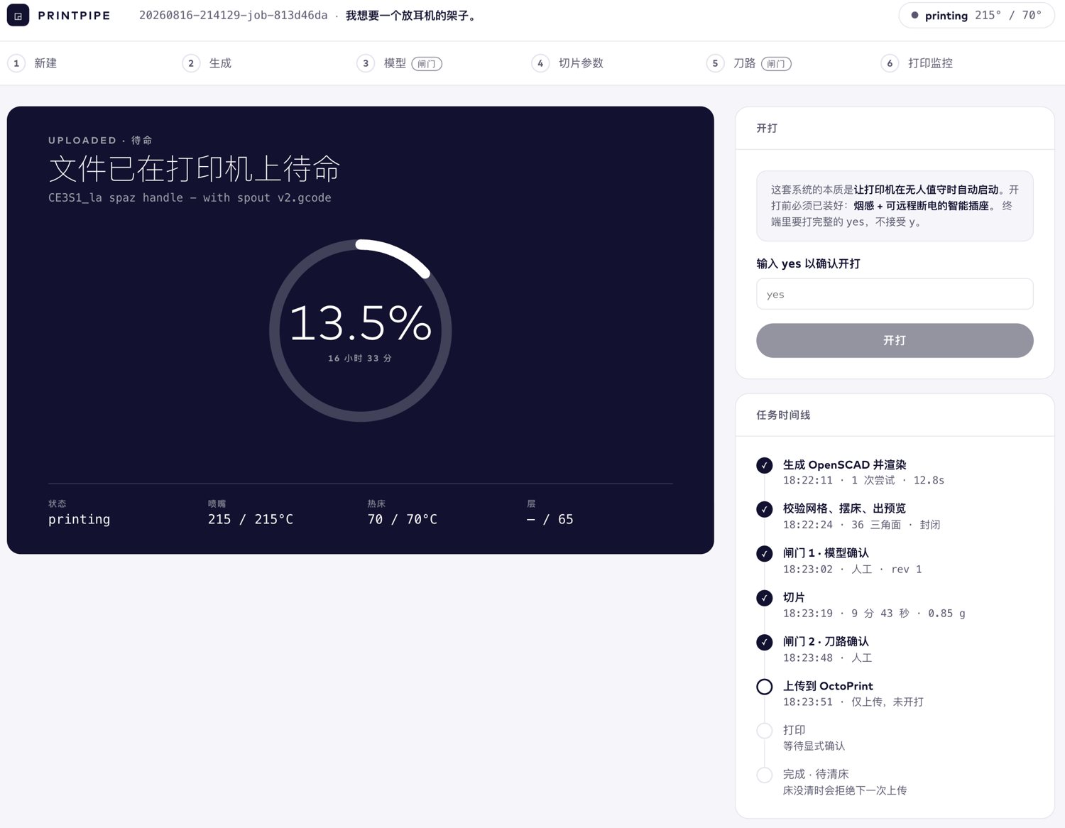
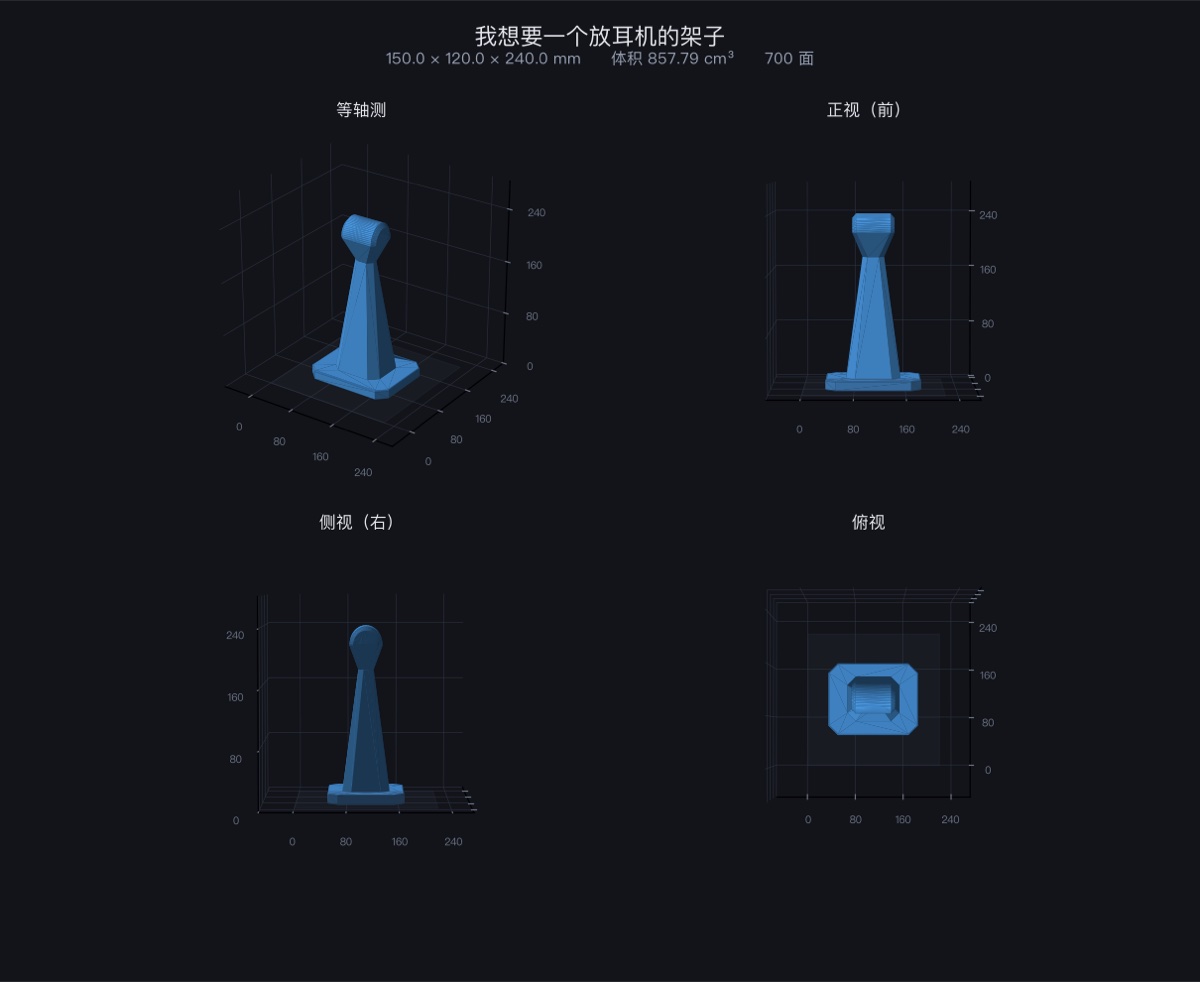
printpipe make "I want a stand for my headphones"Six screens, one shell: new → generate → model gate → slice settings → toolpath gate → print monitor. A sentence goes in one end; a file sits on the printer at the other. Generation, mesh validation, bed placement, slicing and upload are automatic. It stops exactly twice, both times to let a person look at something.
What it removes is everything after modelling: export, open the slicer, pull the SD card, plug it into the laptop, copy, plug it back, scroll the file list.
1 · A sentence

The model comes back as OpenSCAD rather than a finished mesh. That one choice is what makes the rest possible: the geometry stays readable, stays parameterised, and re-renders in about a second.
2 · The model gate
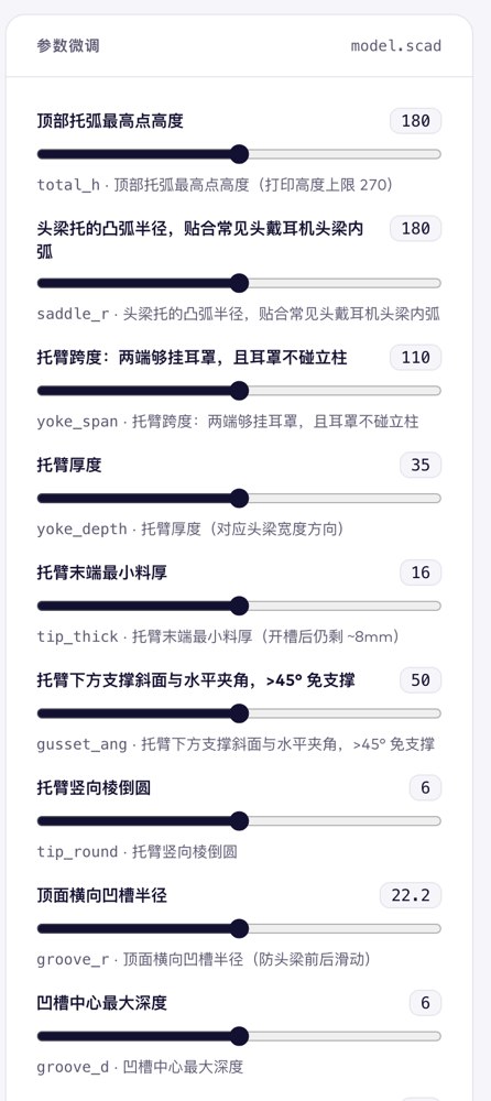
Dragging a slider re-renders through OpenSCAD’s -D in about a second and never
touches the model. Changing the sentence goes back to the LLM and takes minutes.
The interface keeps those apart because they cost orders of magnitude apart, and
blurring them would train the wrong habit.
The slider labels are not authored anywhere. They are the comments already
sitting next to each parameter in the .scad file — the model wrote them, and
nothing had been reading them out.
3 · Slice settings
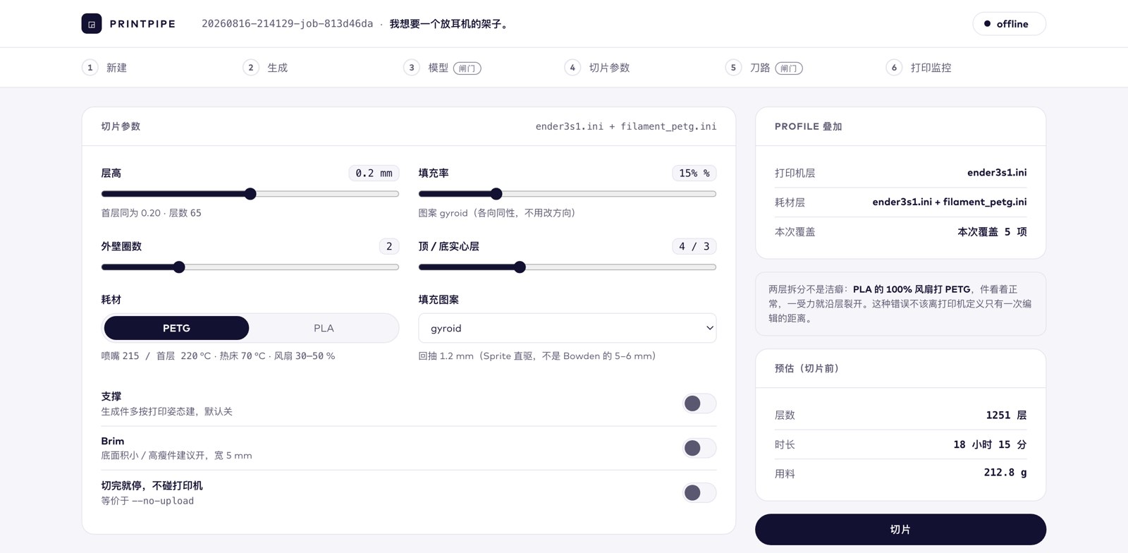
Printer and filament are two profile layers rather than one file, because PLA’s 100 % fan on PETG looks fine until the part splits along a layer under load, and that mistake should not be one edit away from the printer definition.
4 · The toolpath gate
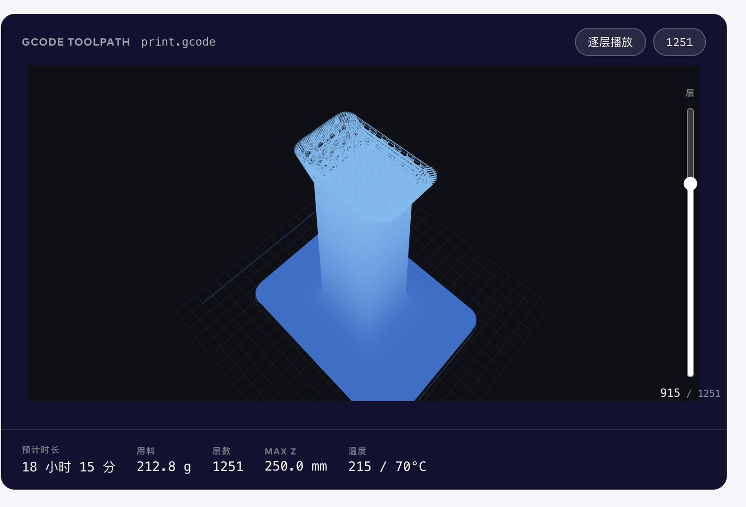
Each segment is drawn with a round cross-section, because a million same-coloured line segments stacked on each other is a smear rather than a drawing.
5 · The printer
Slicing and uploading are separate steps, so a file can be prepared while the
machine is busy. Starting a print requires typing yes in full, in the browser
exactly as in the terminal, and the server checks again before it does anything.
The progress bar only counts the job if the machine is genuinely running this
job’s file; otherwise it shows the queue position and how long the part ahead
still needs.
The library problem
A folder of STL files cannot answer the two questions that come up daily: which
of these are the same mesh, and which are versions of the same part. Filenames
answer neither. station_main_part.stl and Weihao Ipad Holder (1) v5 v2.stl
may be byte-identical; hotshoe v5.stl and hotshoe_updated.stl may not be.
So identity is the sha256 of the mesh bytes, and filenames are demoted to sightings — the same mesh may have been seen at several paths.
Grouping into families is deliberately stupid: strip the tokens that are
obviously version noise (v4, new, 0.05, (1)) and key on what is left. It
over-splits, and that is the failure direction I picked on purpose. ls does
substring search, so a family split too finely is still findable; a family merged
too eagerly hides parts silently.
One rule turned out to matter more than the rest: integers are identity, decimals are versions. The 58 in “53–58 mm adapter” names the part and dropping it merges that adapter into unrelated ones; 3.6 mm, 0.05, −0.01 are almost always a tolerance being re-cut. Getting that backwards splits the adapter family in half, which is how the rule got found.
Where it runs
A CLI and the web flow call the same functions, not two implementations; the only difference is where the two gates get answered. Docker for the toolchain, OctoPrint for the printer, Ender 3 S1 profiles, PETG or PLA.
The screens above are captures of it running — the parameter panel is this
job’s actual model.scad, the slice figures are its real 1251 layers and
212.8 g.